Showing posts with label extruder. Show all posts

Thursday 1 July 2010

Broken bracket breakdown

Whilst printing a 16th set of Mendel parts, my Mendel printed a bed of brackets with bits missing: -


On investigation I found the idler bracket on the extruder had broken, so there wasn't any pressure on the pinch wheel.


It lasted a long time before it broke but clearly it wasn't strong enough. Wade made his in PLA, which is harder and I only use two of the four bolt holes, so mine is under more strain.

I made a stronger replacement. It is thicker and a little bit bigger in the other two dimensions. I also made the holes 4.5mm rather than 4mm so it slides on the bolts easier and I capped the ends of the axle holder as mine tended to slide sideways.


The files are on Thingiverse.

Monday 3 May 2010

Plumbstruder

Brian Reifsnyder asked for volunteers to test his hybrid PEEK and PTFE insulator design, so I used it for the hot part of my Mendel extruder to start with. The drive mechanism is Wade's design.


It worked well at first, requiring little force to extrude PLA, but got harder and harder until eventually it completely jammed. This video below shows that even with the nozzle removed and starting with a completely empty barrel I couldn't push more than about 15mm of filament through it.


The reason was that the PTFE liner had slipped a little leaving a small gap between it and the end of the brass heater barrel.


This makes the extruder jam completely solid. The reason is that PLA goes rubbery above 50°C, so any pressure on it makes it expand width wise and grip the side of the tube. If there is a gap that it can expand into it locks the filament.

I stripped it down, cleaned it out and reassembled it with some washers to hold the PTFE down.


Brian has added a circlip to the design to solve the problem.


I haven't tested this version yet because I ran into another problem before it arrived. When I started using a heated bed for PLA the extruder jammed again. This time it was because the top end of the insulator got hotter than the glass transition of the PLA, so it swelled as it went into the insulator and jammed in the tapered entrance. There was also some leakage around the threads.


The reason it got too hot is a combination of the heated bed, the fact that I used an uninsulated heater with a large surface area, and the fact that the Mendel carriage traps the rising heat.


I decided to try out an idea I had a while ago, which is similar in intent to Brian's scheme. Instead of putting PTFE inside PEEK to stop it expanding I put it inside a 15mm copper pipe. This not only totally constrains it so it cannot swell, it also removes heat from it, shortening the transition zone. I am calling this one Plumbstruder. Here is a sketch of the layout: -


The end of the copper pipe is closed off by soldering an end cap on and then drilling it out to leave a lip to support a PEEK disk which the barrel screws into as well as into the PTFE. That means the PEEK supports the extrusion force, as in Brian's design, but I also use the thread in the PTFE as a seal rather than just having a compression joint.

The copper pipe gets hot so I coupled it to a big heatsink with a copper flange.


I turned this from a solid block of copper a friend gave me (thanks Paul). I soldered it onto the pipe and screwed it onto the heatsink.


I turned the one piece nozzle / barrel from hex stock so it has a nut shaped flange in the middle to make it easy to screw in and also gives the aluminium heater block something to tighten against.


I had to turn down the PTFE to be a tight fit inside the pipe. I was hoping to find a size where the ID of the pipe matched the OD of the PTFE. 22mm copper pipe has an ID of 20mm, so theoretically 20mm PTFE rod would fit. In practice I have found that PTFE rod is about +/- 0.5mm so, unless you were lucky, the fit would not be good enough.

Even with a big heatsink it was getting uncomfortably warm so I added a tiny fan.


I have been using this extruder on my Mendel for a few weeks and it is totally reliable, with no sign of leaking. I think that of all the extruders I have made, this one needs the least force to extrude. I can push plastic through by hand at high speed with ease. For an extruder to work I think the transition zone needs at least two of the following three attributes: short, slippery or tapered. Unfortunately a short transition zone seems to mean using a heatsink, which is not ideal for a moving head machine.

I also think a short melt zone improves the accuracy by reducing the start-stop time. In that respect this design is not ideal, although it is no worse than the standard design.

Sunday 3 January 2010

Extruder broke already

Well my best attempt at making a reliable extruder again resulted in one that only lasted a few weeks! The brass worm pulley that was pushed onto a splined shaft worked loose while extruding PMMA.


PMMA is quite hard work to extrude, but probably no worse than HDPE. On reflection splines into brass are not going to hold the massive force that occurs at 2mm radius. A better idea would be to have a boss on the side of the pulley and use a set screw onto a flat on the shaft. I would also add smaller diameter bosses at each side to meet the centre rim of the bearings. That would automatically position the pulley dead centre.

But to do that I would have to make a new pulley cutting jig and redesign the motor bracket to be a bit wider. I would need a working extruder to make the new bracket of course, so I decided to bodge the existing design.

I drilled out the centre of the pulley to 6mm and then reamed it to 6.4mm. I then turned a steel hub from a piece of hex pillar. I made it about a tenth of a millimetre oversized, added a chamfer to the hole in the pulley and forced it in with a vice, creating a very tight fit.


I didn't trust that to hold on its own so I left a hex flange on the other side and soldered it to the brass: -


Certainly not my best soldering, but bodging is bodging. The hub is twice as wide as the wheel and steel is harder than brass, so it should have a much better grip on the splines. I don't know if it will last or not. The constant back and forward motion of the anti-ooze fix means that if anything is weak it gets worked loose.

With the repaired extruder I made a third lamp shade clip leaving 1mm of the acrylic rod left above the pulley, how lucky is that?


Then I pushed my luck too far. When I bought the 3mm PMMA rod I also got a 2mm rod to compare results. Stiffness of a rod is a fourth power on diameter I think, so 2mm filament is five times more flexible than 3mm.


This would certainly be feasible to use in coils as it has a similar minimum bend radius to 3mm PLA, we just need to find somebody to supply it in that form at a reasonable price. 2mm rods are even more expensive than 3mm rods, £1.24 on eBay as opposed to £1.49, but are only 44% of the volume!

I decided to give it a try in my newly repaired extruder by printing a whistle. I had to scale it down because with 0.4mm filament it would use more than 1m of 2mm filament, so I printed the same g-code using 0.3mm filament and scaled the dimensions accordingly.

It managed to print a couple of layers and then the extruder jammed. I think the problem is that with a 3.6mm bore and 2mm filament there is too much of a gap, so molten plastic can flow upwards and freeze in the cold part of the tube above the taper. I think it would work fine with an extruder designed for 2mm filament. The drive mechanism just about works because although it does not have as much grip, it only needs 44% of the force that 3mm filament needs. The barrel and heater block would need a smaller bore though and could be made smaller. Similarly the smaller motor I used before would have plenty of torque, in fact a high torque NEMA14 should work.

So there are a lot of advantages to using 2mm feedstock like commercial machines do, BUT stiffness falls as a forth power, but force required only falls as a square law, so I expect soft plastics like HPDE, PP and PCL may buckle when being fed. Certainly the gap between the pinch wheel and the barrel entrance would need to be very small.

I fixed the jam by putting a drill down the hot barrel and hitting it with a hammer. That fixed it and I hand fed some ABS before reassembling the extruder. After assembly it would not work at all. The thermistor had shorted out to the metal work!

Nothing much to see from the outside, just a weird furry slimy deposit on the back of the AL tube and a green stain on the thermistor lead that was shorted.


I cannot get to the thermistor or heater without removing the PTFE cover, but that can't be removed without unscrewing the barrel, another slight design flaw. If I had tapped the stainless steel pipe all the way up I could just unscrew it from the AL tube that surrounds it, but it is really hard work tapping stainless steel.

I unscrewed the barrel while the extruder was hot to reveal this mess: -


The plastic that leaked when I first built the extruder has been stewing for weeks and has boiled down to something resembling bitumen. I expect the more volatile products condensed on the cold AL tube above it forming the Vaseline like deposit.

I couldn't tell why the thermistor was shorted because it came away with the PTFE cover. The Cerastil that I glued it in with seems to have decomposed in the chemical soup around it. My last few attempts at sticking thermistors with Cerastil have not been very successful. I am not sure if I mixed it to the wrong consistency, or if it is now too old to cure properly. It doesn't look any different, but instead of rock hard cement I seem to get something crumbly.

I cleaned it all up and stuck the thermistor back in with RTV silicone. I am sure it is not as conductive as Cerastil, but over such a short distance (between the thermistor and the wall of the hole it is in) I am hoping it will not have much effect.

I made the hole for it a bit deeper and opened out the top so it was big enough to accommodate the PTFE sleeving as well. That should keep it from touching the metal. It is surprisingly difficult to glue something into a small hole with a viscous glue. It is hard to get the glue to go down the hole without leaving an air pocket. A better idea might be to drill out a small screw, all the way through, fill it with glue from both sides. Then when it has set simply screw it into a tapped hole in the heater block.

I am waiting 24 hours for the silicone to cure now, so back to work tomorrow and less blog posts.

Monday 21 December 2009

Reliable extruder at last?

... well only time will tell but I have now fixed all the teething problems on my "no compromise" extruder.

The first problem was it was leaking plastic. I simply tightened the thread about another quarter turn while hot. The problem started when I had to dismantle it to replace the first resistor that I damaged. When I put it back together I didn't get it tight enough as it is difficult to judge when full of plastic and hot. The seal relies on the fact that the relatively sharp edge of the stainless steel tube can bite into the softer aluminium. It seems to work when tightened enough.

The other problem was that the motor would skip steps in the middle of a build for no apparent reason. It seems the amount of force required to extrude varies wildly for which I have no explanation, but I did find some mechanical issues that were reducing the torque available.

I noticed the gear would always be in the same position when the motor skipped. I found that the grub screw was catching on the bearing housing. You would expect it just to grind the PLA away, but PLA is very hard, so it would take a very long time to do so. I increased the clearance around the wheel hub and also around the moving part of the ball bearings.

Another issue was that both the worm and the gear were slightly off centre on their shafts, so when the two high points coincided they would bind. The hole in the Meccano gear is slightly bigger than the 4mm shaft it is on, not sure why. The hole I drilled in the worm is 5mm but the MakerBot motors have imperial shafts about 4.75mm, so that was even more eccentric. Added to that was the fact that the motor bracket has a slight warp to it angling the shaft down a little. All these things conspired to make it stiff to turn once per revolution. I fixed it by tightening the bottom motor screw tight and slackening the top two a little. That was enough to reliably extrude PLA. Making the motor holes into slots would make things less critical.

Although the extruder was working reliably for PLA I wanted more torque in reserve, so I switched to a higher torque motor more suited to my driver chip. The Lin motor I was using was rated at 0.3Nm holding torque for 2.5A, but my controller can only manage about 1.5A without some better heatsinking. I switched to the Motion Control FL42STH47-1684A-01 which gives 0.43Nm at 1.7A. So at 1.5A I have gone from 0.18Nm to 0.4Nm, i.e. doubled the torque and also got the right shaft diameter to fit the hole I drilled in the worm.


The only downside is that it is bigger and heavier, not really an issue on HydraRaptor.

To give it a thorough test I printed off a couple of Mendel frame vertices.


These take about 2 hours each with 0.4mm filament, 25% fill, double outline at 16mm/s, infill at 32mm/s. Six are needed in total.

I still have to test it with HDPE and PCL., I know it works with ABS.

Wednesday 4 November 2009

No compromise extruder

I have settled on using vitreous enamel resistors embedded in an aluminium block for the heater. I think they are the easiest heater to make and likely to be the most durable. They also work fine with simple bang-bang control, whereas it would appear that the Nichrome and Kapton version requires PID.

One of the aims of my new design is to reduce the amount of molten plastic to minimise ooze. Also less molten plastic means less viscous drag. I also wanted to reduce the thermal mass (to reduce the warm up time) and completely cover the hot part with insulation to allow a fan to blow on the work-piece without cooling the nozzle.

To achieve these aims I switched to a smaller resistor (same resistance but less wattage) and mounted it horizontally rather than vertically. There is some risk that the resistor may fail but I think as long as it has good thermal contact with the aluminium block, so that its outside temperature is less than 240C, then I have a good chance it will last.

The smaller resistor also means a much smaller surface area so less heat is lost. T0 keep the molten filament path as short as possible I combined the heater and the nozzle and made it from one piece of aluminium. That also gives very good thermal coupling between the nozzle tip, the melt chamber, the heater and the thermistor.


I turned it out of a block of aluminium using my manual lathe and a four jaw chuck, but I think I could also mill it out of 12mm bar using HydraRaptor.

A feature that I have used on my previous extruders is to cover as much of the nozzle as possible with PTFE. That stops the filament sticking so that it can be wiped off reliably with a brush. It also insulates the nozzle.

My previous nozzle cap implementations have been turned from PTFE rod. The downside of that is that the working face, that has been cut and faced on the lathe, is not as smooth and slippery as the original stock.


To cover the face of this version I used a 3mm sheet of PTFE so it has the original shiny surface.


Normally PTFE is too slippery to glue so my original plan was to screw it on with some tiny countersunk screws. However, the sheet I bought was etched on the back to allow it to be glued, so I stuck it on with RTV silicone adhesive sold for gluing hinges onto glass oven doors.


To insulate the rest of the heater I milled a cover out of a slice of 25mm PTFE rod.


I normally stick items to be milled onto the back of a floor laminate off-cut using stencil mount spray. I didn't think that was going to work with a PTFE cylindrical slice that is only a little bigger than the finished item. Instead I milled a hole in a piece of 6mm acrylic sheet that was already stuck down with stencil mount. The hole was slightly smaller than the PTFE so I faced it and chamfered it on the lathe and then hammered it in.


I roughed the shape with a 1/8" end mill and then sharpened the internal corners and cut the slots for the resistor leads with a 1mm end mill. I tried to mill the whole thing with a 1mm bit but it snapped due to a build up of burr in the deep pocket. On reflection it was silly to expect to be able to mill deep pockets with a 1mm bit and of course it is much faster to rough it with a bigger bit.


I used my normal technique of taking 0.1mm depth cuts at 16mm. That allows me to mill plastic with no coolant, but I expect I could have made much deeper cuts in PTFE. It mills very nicely, probably because it is soft and has a high melting point and low friction.

I haven't done any milling for a long time so for anybody new to my blog here is my the milling set-up: -


It is simply a Minicraft drill with some very sturdy mounts. The spindle controller I made originally would need its micro replaced as the one I used has a bug in its I2C interface. Instead I just connected it to the spare high current output on my new extruder controller.

The remaining part of the extruder is the stainless steel insulator.


I made the transition zone shorter than the last one I made because I wanted all of the inside of the transition to be tapered. The aluminium sleeve carries away the heat from the cold end of the transition to an aluminium plate that forms the base of the extruder. That in turn carries the heat to the z-axis via an aluminium bracket. I used heatsink compound on the joints.

Here is a view of the bottom half of the extruder: -


And here is a cross section showing the internal details: -


So that was the plan, what could go wrong? Well everything really! The first problem was that the resistor shorted out to the aluminium block. The smaller resistor only has a thin layer of enamel over its wire. Normally I wrap aluminium foil round it to make it a tight fit. I didn't drill the hole big enough so it was a tight fit with only one layer and pushing it in abraded the enamel. The solution would be a bigger hole and more layers of foil, but I just glued it with Cerastil as a quick fix. Of course it only failed after I had fully assembled it and run some heat cycles so I had to strip it down again to fix it. Not easy once the wiring has been added.

The next problem is that it leaks. I think it is because I dropped the extruder when I was building it and bent the thin edge at the end of the stainless steel barrel. That forms the seal with the heater block, so even though I straightened it I think the seal is compromised. I keep tightening it and thinking it is fixed but after hours of operation plastic starts to appear at the bottom of the PTFE cover.

The other problem is that mostly it extrudes very well, I now do the outline at 16mm/s and the infill at 32mm/s, but sometimes the force needed to push the filament gets higher and causes the motor to skip steps, or the bracket to bend so far that the worm gear skips a tooth.

I have made several objects taking between one and two hours and it worked fine. Other times, mainly when I was making small test objects with Erik, it will completely jam. Actually it seems to jam when it is leaking badly, which implies the pressure of the molten plastic is much higher as well as the force to push the filament. The only explanation I can think of is there is an intermittent blockage of the nozzle exit. More investigation required.

Sunday 25 October 2009

Worm drive

I have spent a long time trying to make an extruder that is reliable, performs well and is cheap and easy to make. My last design fits most of those criteria but I have doubts about how long it will last because I am putting a lot of torque through the plastic gears of the GM17 gearbox. These doubts were heightened when a tooth snapped in a GM3 gearbox that I have been using for a long time.

I decided to make a new extruder for HydraRaptor concentrating on performance and reliability. I have tried to pull together all the results of my experiments to pick the best solution for each part of the design, regardless of cost and ease of building. The result is a "no compromise" design that has taken me a long time to make. Hopefully it will be reliable so that I can move on to exploring other things.

The design criteria for an extruder for HydraRaptor are a bit different from Darwin. The weight of the extruder is far less important because it is a moving table machine (rather than moving head). The z-axis is a big slab of aluminium so I don't need a heatsink or fan, I can just conduct the heat away.

I found that the best form of traction is a "worm pulley". Screw drive has slightly more grip on softer plastic but is far less mechanically efficient. It also has the nasty habit of making the feedstock rotate in some cases and also generates dust.

The pulley can impart in excess of 100N force on the filament before it slips, so to have the grip as the limiting factor we need a motor that can provide that amount of torque. The pulley has a radius of 6.5mm so that equates to 0.65Nm. I could do that with direct drive off a NEMA23, but even with micro stepping a single step is quite a lot of filament: 13mm × Ï€ / (200 × 8) = 0.025mm. That doesn't seem much but 0.5mm filament comes out 36 times faster than its 3mm feedstock goes in, so that is almost 1mm extruded per step. That seems way too big for accurate control to me, so some gearing is necessary.

A worm gear is attractive because it gives a big reduction in one step so I came up with this arrangement: -


The pulley is on a 4mm splined shaft supported by two ball bearings. The gears are Meccano gears which are readily available. I couldn't find any other metal gears at reasonable prices. I had to drill out the worm wheel to fit the motor shaft. I filed flats on both shafts to allow the grub screws to grip.

This bearing cover holds the bearings in place and guides the filament: -


The assembly is clamped together by M5 hex head bolts that are captive in the plastic.


You can see the top of the stainless steel pipe that the filament feeds into. It has an aluminium outer sleeve to conduct the heat away from the transition section, rather than a heatsink. More on that later.

A skate bearing is used as a roller to apply pressure to the filament: -


A piece of M8 studding forms the axle. It is held in place just by friction. The bearing is centralised by cheeks on the plastic which are clear of the moving part.

The pressure is applied by springs and M5 wingnuts: -


The nuts on the bearing cover prevent the roller from meeting the drive pulley when there is no filament. That allows filament to self feed easily simply by inserting it into the hole in the top.

I measured the performance by attaching a spring balance to the filament and measuring the force at which the motor stalled for a given current: -


The motor is a NEMA17 rated at 0.3Nm holding torque with two coils on at 2.5A. The reduction ratio is 40:1, so I expected to only need about 0.637 / 40 to give a 100Nm pull. I was disappointed to find that I needed 1.5A to pull 10Kg.

With sinusoidal micro stepping drive the holding torque will be 0.7 times the two coil on value. I.e. 0.21Nm @ 2.5A, so 0.126Nm @ 1.5A. The torque from the pulley is only 0.016Nm assuming a reduction of 40:1, so the worm drive is only about 13% efficient if I have got my calculations right. Before I greased it, it was only half as efficient, so worm gears certainly waste a lot of effort in friction. The article here says they are between 98% and 20% for ratios 5:1 to 75:1, so I am probably in the right ball park. There will also be some friction in the bearings and pull out torque will be a bit less than holding torque, even though it is only rotating slowly.

So it reaches the target torque but with far less efficiency than my version with the tiny motor and the GM17 gearbox.

The other disappointment is that is is quite noisy, even when micro-stepping. That is simply because the z-axis couples any vibration to the wooden box behind it that then amplifies it. I
am tempted to fill it with something to dampen it down.

So this half of the extruder seems to perform, and it should be reliable because there is not much to wear out, except perhaps the worm gears, that is where most of the friction is and they are only made of brass.

I will test the bottom half of the design tomorrow.

Wednesday 26 August 2009

Fast extruder

I put together my new extruder controller, the worm pulley drive mechanism with the GM17 tiny stepper hack and the stainless steel extruder with heatsink and ducted fan to make possibly the most complicated extruder design yet!


You can see a better view of the drive mechanism fitted on another extruder base here: -


Here is a reminder of what the heater assembly looks like: -


The heatsink is cooled by a tiny fan. When run from 12V it is very noisy and way too powerful. With my new controller I can run it with PWM just a bit faster than its stall speed. That keeps the noise down and still gives more cooling than needed. I attached a thermistor to the heatsink by gluing it into a crimp tag with J-B Weld.


I can tell the controller to keep the temperature below a specified level by turning the fan on and off. I set the trip point to an arbitrary 35°C. It will even turn it on when the extruder is idle, much like the radiator fan of a car runs after the engine is switched off. This is needed to ensure PLA will never soften and jam in the cold part of the tube.

I run the tiny stepper motor at about 300mA to keep it cool enough to touch. It will take more current than that but runs very hot. A good design would use a single fan to cool the motor and the heatsink.

I ran the motor with micro stepping, so even though it has a 15° step, that gives 192 steps per revolution. The GM17 gearbox has a reduction of 228:1 giving a massive 43,776 steps per revolution of the worm pulley. That seems a lot, but the diameter of the pulley is 13mm, so one turn is 40.84mm of feed. That gives 1072 steps per millimetre. In comparison I have been using an 816 step shaft encoder and an 0.8mm pitch thread, which gives 1020 steps per millimetre, almost the same.

I started extruding ABS with my usual feed rate of 16mm/s for 0.5mm filament, which is 3.14 mm3 per second. I kept doubling it until it failed, which was 128mm/s if I have got the calculations right. At that point it mostly worked but something was slipping occasionally. I think it was the clutch in the gearbox. Backing off to 64mm/s it works fine. That is four times faster than the GM3 manages with a screw drive. It is too fast for HydraRaptor but I reckon my Darwin could go that fast. I have no idea what the build quality would be like but it would get the time to print one down to about 24 hours.

Here is a video of it spewing out plastic.

Fast Extruder from Nop Head on Vimeo.

It isn't mechanically compatible with HydraRaptor without making a new bracket to mount it on the z-trolley, so I haven't made anything with it yet.

Monday 13 April 2009

Dinosaur?

This may be an evolutionary dead end, with the move to stepper motors and pinch wheels, but I wanted to try a couple of things that have been on my "to try" list for a long time.

The main issue that I have had with the pump part of the original extruder is that the bearings wear out fairly quickly. Both the half bearings themselves and the lands on the shaft. One problem is that being only half bearings, any lubrication soon gets carried away by the plastic.

The best lifetime I have had is with stainless steel bearings and a stainless steel shaft. The downside of a stainless steel shaft is that you cannot solder a nut on to provide the drive. I have found two ways round this:-
  1. Use a hex head bolt. For some reason stainless steel bolts never seem to have thread all the way to the top. Since the thread needs to be sharpened with a die anyway, it can be extended at the same time. It is hard work tapping stainless steel though. You need a split die, set to its biggest diameter to start with, and you need cutting compound. The hex head allows you to get a good grip to stop it turning and the original thread makes it easy to start off square.
  2. Drill through the nut and shaft and insert a pin. If, like me, you break lots of drills then broken drill shafts make perfect pins. I now buy drill bits in packs of five or ten!
I replaced the two half bearings with three ball bearings. At the top is an M5 bearing to take the axial thrust. At the bottom I use two M4 bearings as rollers to take the radial load.


The downside of this arrangement is that you still need to turn a land on the bottom of the shaft. It could probably be done with a file and drill though. It actually works without removing the thread, but I expect it might wear away the rollers.

This design works but there are a few things I would change if I built another: -
I made it compatible with the existing filament guide to avoid having to reconfigure my machine for HDPE. Ideally the screw holes at the bottom end need to move out to allow longer bolts to hold the rollers and the size needs increasing from M3 as the threads strip eventually.

I left clearance to allow the top bearing to be inserted from below, but left no access to the nuts. Consequently it was very difficult to assemble and I had to make undersized nuts.

I used the smallest outside diameter bearings I could find for the given inside diameter. That was a mistake because it is hard not to foul the outer part of the bearing with a washer as the moving part is so small. Star washers seem to just grip the inner and provide enough standoff to clear the outer. I used counter sunk heads to clear the outer face of the rollers. I expect larger diameter bearings use bigger balls, so perhaps have higher ratings.
All easy things to put right with a design iteration.

Another thing I have been meaning to try is the GM17 gearmotor. I have had some for a long time, but without a second shaft, adding a shaft encoder is not trivial, as it is with the GM3. Solarbotics now sell a cheap magnetic encoder that fits inside the casing, making it a more attractive proposition.

To fit the motor in place of the GM3 a new mounting bracket and a shorter version of the shaft coupler is needed.


Here is the completed pump: -


And here it is built up into an extruder: -


I am waiting for the magnetic encoder to come from Canada so I tested it open loop with a couple of bench power supplies.

The GM17 is a bit quieter than the GM3, but not that much when heavily loaded. It extrudes at a similar rate, but the speed seems to vary a lot with load, so it would be useless without closed loop control. It seems to labour and get quite hot at 12V, so I don't imagine its life would be a lot better than GM3. It overruns a lot when the power is disconnected, so it would need a full H-bridge and reverse thrust to get decent stopping.

I still have lots of things to try: stepper drive, a roller instead of the filament guide, an offset screw drive to avoid the rollers.

Friday 20 March 2009

Pulling power

There are a lot of extruder drive methods kicking about at the moment, so I decided to evaluate a few by measuring the amount of force they can apply to the plastic before it slips. Rather than build complete extruders, I just made mock ups of the final drive and measured the force they could apply to a spring balance.

My first test was using a splined shaft as a minimalist pinch wheel. This was inspired by Adrian Bowyer's knurled design. I wanted to try it because you can get steppers with splined shafts, so it would be a ready made solution rather than needing a knurling tool and a lathe. I used a 4mm splined shaft that I had lying around. Being that small means the torque required to turn it is quite modest.


I mounted it between ball bearings, which were a press fit into a plastic housing: -


The Meccano gear is just acting as a knob at the moment. I pressed the filament onto it using a skate bearing acting as a roller.


This is my sophisticated test set-up: -


I wind the knob by hand until the filament slips and observe the maximum force for each type of plastic. I noted that tightening the screws past the point where the splines are fully sunk into the filament does not increase grip, it just flattens the plastic more and needs more torque.

The results were: -

PCL2.5Kg
HDPE3Kg
ABS5Kg
PLA7.5Kg

Not surprisingly the grip gets better with the harder plastics. Unfortunately PCL and HDPE need quite a lot of force to extrude, so this drive method is not really good enough for them. A larger diameter shaft should give more grip due to a larger contact area and possibly deeper splines.

The next method I tried was Zach's pinch wheel drive using a square tooth timing pulley.


This needs much higher torque, but gives a much better grip, particularly with the softer plastics. As you might expect the torque is very uneven as the pulley moves from tooth to gap to tooth.

With HDPE, it pulled out of the chuck before slipping, so I switched to an alternative connection to the spring balance.


The results were: -

PCL4Kg
HDPE10Kg
ABS8.5Kg
PLA>8Kg

PLA slipped from the chuck and snapped when using the alternative coupling, so the true figure is probably higher, but it far exceeds the force needed to extrude PLA anyway.

HDPE has shot up the ranking because although it is quite soft and very slippery, if you can get a grip on it, then it is very tough.

Only PCL is marginal compared to the force needed to extrude it.

Zach uses a bigger opposing wheel, so maybe that would give a bit more contact area.

The next thing I tried was the original screw feed design, to get a benchmark, as that is what I have been using so far. It can feed all four plastics reliably, the only problems I have had with it are that the bearings wear out after 100's of hours of use, easy to fix by using ball bearings.

The implementation I used for the test has phosphor bronze bearings and a stainless steel screw. Rather than use threaded rod and try to fasten a nut on the end, I used a hex head bolt. Long ones don't come with enough thread, but you have to run a die over it anyway to sharpen the thread.


It is very hard work tapping stainless steel. For my first attempt I made the mistake of turning the top bearing land before tapping, so that I didn't mar the thread in the lathe chuck. Even though I made the land 3.5mm diameter rather than 3mm, the torque required to tap it actually twisted the shaft where it was turned down. My nice polished bearing surface became a dull and wrinkly spiral!

The other half of the drive is made from HDPE. I think this is a big factor in making it work well as the HDPE is very slippery and doesn't seem to wear much.


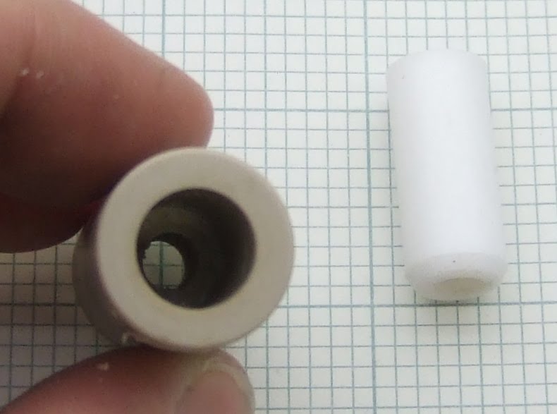
A self tapping screw secures the PTFE insulator in the clamp.

The other crucial modification is to angle the screw so it bites gradually at the bottom by spacing the top with two M3 washers and only having two very strong springs at the bottom. Here it is under test: -


The grip was too high for my chuck, and the coupling shown above kept snapping PLA, so I made a brass coupling.


This has a 5mm bore that narrows to a 3mm hole in the bottom. I melt the end of the filament to a blob and feed it through the top.

The results were: -

PCL9Kg
HDPE>12Kg
ABS>12Kg
PLA>12Kg

My spring balance has a maximum reading of 12Kg.

So the screw drive has dramatically more pulling power. It is however, very mechanically inefficient. A lot of torque is wasted by the friction cutting the thread. This can be reduced by shortening the amount of thread engaged. I plan to try it with an opposing roller instead of the HDPE filament guide.

The threaded drive does do more damage to the filament, but the only downside of that seems to be that some dust is produced. The lower filament has been chewed by the timing pulley.


Two other drive methods I plan to try are a knurled shaft and Andy Kirby's worm wheel. That looks like it might have similar grip to a thread, but without as much friction. A lot harder to make though.